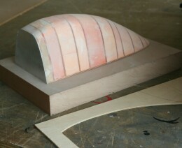
The vac-formed canopy
Tuesday, 2nd October, 2012
By mid-summer of 2012 the bulk of the work on my P51-D had been completed, yet several hurdles remained, one of which was the sliding cockpit canopy. I was aware that there were only two routes by which to approach this: The transparent part would have to be either blown or vac-formed, and both would need equipment and skills that I lacked.
During the many months in which I pondered how best to approach a task that might make or mar my handiwork, I turned for help to the Large Model Association which has a superb website crammed full of sage advice about building and flying giant-scale aircraft. I am indebted to the LMA, for within days of my post appearing on their technical forum pages, I received chapter and verse on the techniques I needed. My special thanks go to Phil Clark and Mike Booth who respectively championed the two alternative approaches. I knew that Mike was right in insisting that only blown-PETG would give flawless optical quality, yet I was hesitant, doubting my ability to manufacture the necessary tooling; on the other hand, Phil’s superbly detailed description and photographs of the entire vac-forming sequence was, I thought, achievable, and much of what follows is inspired by his notes.
I also want to thank Arthur Bentley for providing another essential pre-requisite… reliable sections of the P51-D’s Perspex canopy. And here I admit to blatant infidelity: The Mustang, as preserved at Hendon, has the blown bubble hood; mine sports the earlier, flatter version as delineated in Arthur’s sections. I accepted a compromise, for even had I possessed drawings of the blown version, its shape, due to undercut, would have been incompatible with the vac-forming process.
It is no exaggeration to claim that 95% or more of the work involved in producing a vac-formed piece such as this goes into the tooling. Using the method advocated by Phil Clark, there are three stages: an accurate light-weight model of the piece (1), from which a mould is produced (2), which is used to pour a high-density epoxy or polyurethane resin tool (3), the latter being necessary to withstand the combined heat and pressure inherent in the commercial vac-forming process.
I made the initial plug using a technique similar to that employed to construct the core of the airframe, but instead of infilling between the ply formers with balsa wood I used lightweight modelling foam. That is where the similarity ends, for to achieve the essential high precision finish, the model has to be thinly laminated with at least two layers of resin impregnated glass tissue. The result must be a near perfect surface finish, for any flaws inherited by the resin tool will be very difficult to rectify and will almost inevitably transmit to the final product.
At this stage, I departed from Phil’s method, choosing silicone rubber for my mould in preference to glass fibre, only because I was more familiar with the technique. For large components, the rubber lacks the rigidity of a GRP shell mould, but I reasoned that by shoring up the external faces I could guard against any noticeable flexing during its filling. However, I had not reckoned on a further problem: tiny bubbles in the active surface of the silicone rubber left by trapped air. These spell death for the process, because vac-forming with clear PETG (Polyethylene Terephtalate Glycol-modified) is extremely unforgiving. Even minute blemishes almost invisible to the naked eye (and including airborne dust) will make themselves apparent in the finished piece! Thus, nervous of my first attempt, I made a second mould (and even a second resin tool), but with little or no improvement to either. Make no mistake – the consumables required in this process are not cheap. Suffice it to say that by the time I had finished, I had ample reason in time and money to rue my decision to deviate from the recommended path!
There are some savings, however, because the resin tool does not have to be solid. Indeed, a core is preferable since certain two-part resins are highly exothermic when used in quantity. I roughed my core from modelling foam and suspended it inside the rubber, allowing a resin thickness of 1/2-in. to 3/4-in. all round. I used Alchemie two-part epoxy resin, which is relatively slow curing but provides a dense and resilient product that can, if needed, be polished to a fine finish, although too fine a finish can actually be detrimental to the process.
The next stage was to consult with Derek at Sarik Vacform in Bristol, a small commercial operation with long experience of bespoke jobs for model makers. I had managed to polish most of the offending micro-bubbles out of the final tool, and since I would need only three or four pulls at most from my plug, Derek was reasonably confident that any residual imperfections could be stopped with fresh automotive filler. He also advised me to afix a 10 mm or so plywood base to the tool to aid pull-down and to add a 15-20 degree slope to the front end, so that the piece would release without damage.
I travelled to Bristol in early August with both my plugs for good measure, and by the time I had finished the cup of tea I was offered, the job was done. What had taken weeks in the preparation was executed in minutes, and I left with four pulls of my canopy in two thicknesses of PETG. This allowed ample contingency for error as well as a sacrificial canopy over which to safely build the metal frame. Yes, at the end of the day the vac-form option is not optically flawless, but one has to look hard to see any imperfections. All in all, I am well content with the result.


Previous post

VHF and battery packs
Next post

Canopy framework

