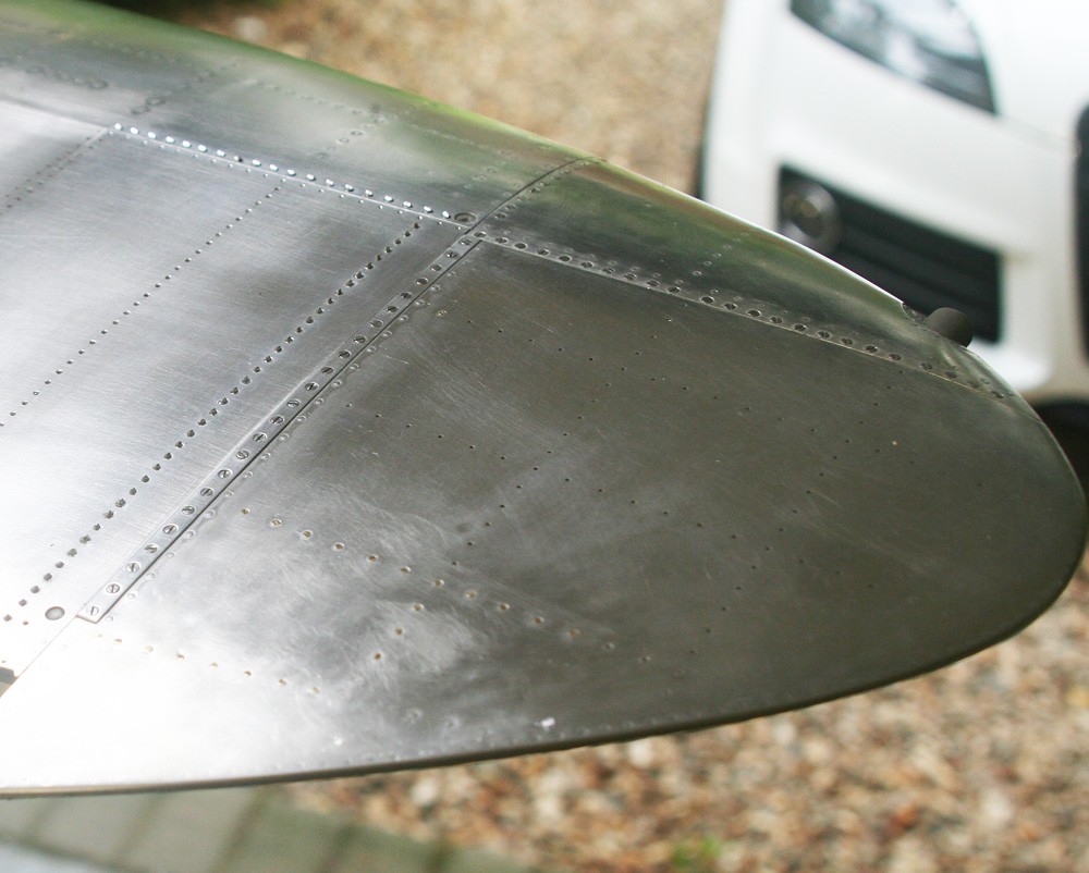
The wing tip skin
Monday, 7th November, 2016
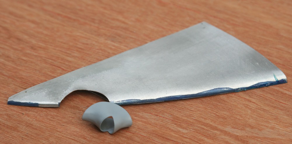
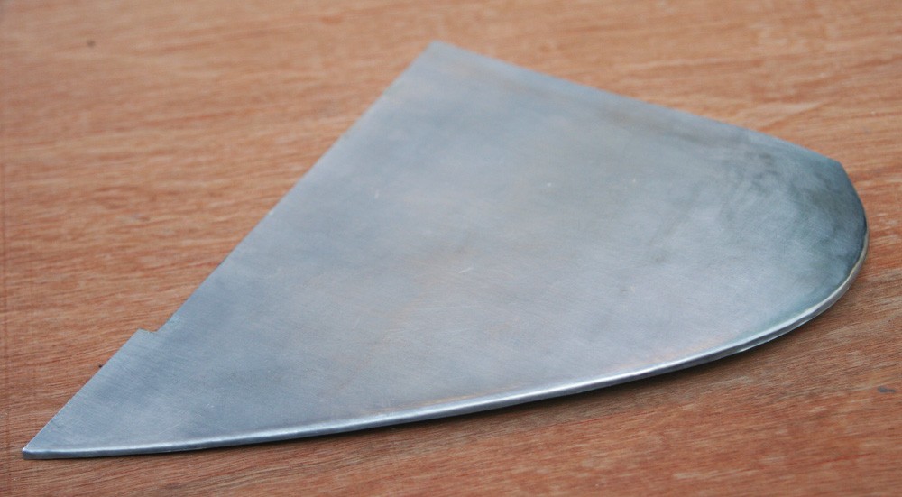
The Spitfire’s wing tip (which is detachable in the full sized machine) has two skin parts plus a narrow fore-aft reinforcing strip per side, and compared to the leading edge they are easy to do. As before, a little heat annealing is helpful around the outer periphery of the plates but after that the metal, if closely trimmed, snugs down nicely along and around the fining out wingtip.
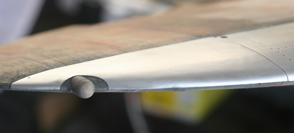
The navigation light fairings do not overlap the wing skin. So by making these first (as described on my previous page), I was able to use them as templates for scribing and cutting the underlying litho plate, thereby obtaining neat and tidy abutted seam lines (the seam is actually toggled in the real aircraft).
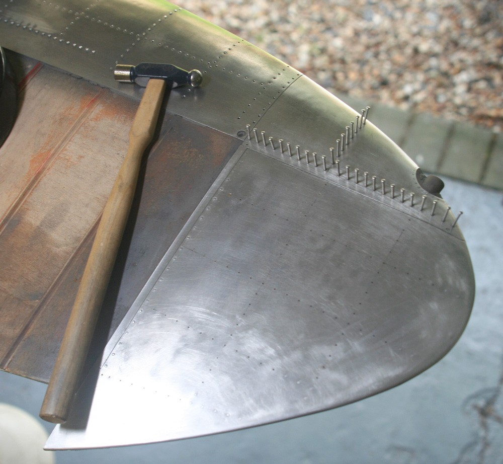
The only thing to say about the bracing strips is that they are made of thicker material, so that they stand perceptibly proud of the surrounding wing skin. I used 0.75mm aluminium sheet.
The single perceptible difference between the wingtip skin and that covering the rest of the main-plane is that in the full size aircraft the former is secured to a wooden framework by no fewer than 80 wood screws per panel. The above-mentioned reinforcing piece is also perforated by a row of 24 larger screws. This is not only time consuming for the model maker but also costly: Tiny 16 and 14 BA screws purchased in their hundreds run up a hefty bill very quickly.
There is also another drawback: Making neat and consistent countersunk holes in thin aluminium sheet (the litho plate I use is no more than 11 to 12 thou thick at most) is not easy. And if the countersinks are not consistent, especially where closely spaced, and the screws do no present perpendicular to the metal surface, the finished work can look ghastly. (For anyone interested, I will be posting a brief description of the techniques I use for this on my ‘Aired and Shared’ pages of this website shortly).
